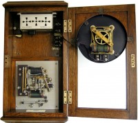
GENTS’ DAC CHRONOMETER FIG. C283
==================================
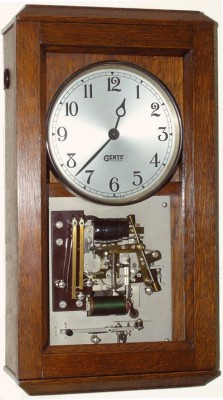
The Gents’ DAC Chronometer was designed in 1934 to take advantage of the long term accuracy of the A.C. Service Mains without the disadvantages of interruptions or breakdown of this A.C. Power Supply.
The Gents’ DAC Chronometer is a Transmitter or Masterclock, equipped with a lever to adjust the whole circuit to DST.
Patents:
421,744 and 421,746 1934
====================
Dimensions: Height: 19″
Width: 10″ Depth: 5″
DESCRIPTION:
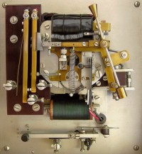
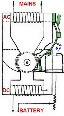
The synchronous motor has two rotors, two sets of pole-pieces and also a toothed wheel which forms one contact of the switch for the DC coil.
The AC Mains coil is at the top and has the front set of pole-pieces. This is a conventional non-self starting 50Hz 240 volt synchronous motor.
The lower green DC coil is on the back set of pole pieces and is a series motor on the rear rotor.
The resistance is 4 ohms and she runs from a 6 volts battery.
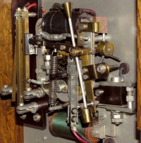
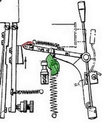
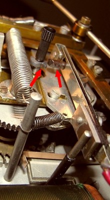
The motor drives a reduction gearing to a wheel rotating once a minute. This wheel has a double cam (in green) which operates the contacts every half minute. The cam slowly raises the gravity arm. As it rises, the toggle at the left end of the gravity arm parts from the ramp on the contact arm and flips into a horizontal position pulled by a spring. The cam then lets the gravity arm drop and as the toggle (red) runs down the ramp it pushes the right hand contact arm to the left hand arm and closes the contacts. The counterbalanced delay arm moves slower than the gravity arm and rotates clockwise until it hits the pin at the lower end on the gravity arm. The impulse given jolts the gravity arm and the toggle flips over into the vertical position allowing the contacts to open.
The little black knob is used to start the clock. A double cam on this arbor operates the vertical contacts which are brought into contact with the cam by the retard / normal / advance switch lever under the movement. this is to adjust the whole slave circuit to DST and back.
The switching in of the DC motor on the failure of the Mains is effected by the weighted lever (green) at the top right of the movement.
When the clock is running from the Mains, the block on the top of the lever is held against the pole piece of the AC coil by magnetic attraction. The other end of this weighted lever holds an isolating block that, as long as the block on the top of this lever is attracted to the AC coil, prevents a contact spring from making contact with the toothed wheel of the DC motor. In the event of a Mains failure the block at the top is released and the weight falls. This moves the insulated other end of this weighted lever away from the contact spring allowing a contact to be made between the end of the spring and the toothed wheel. As the contact is successively made with each tooth of the wheel, a current flows thought the lower coil, causing the rotor to rotate at more or less the normal AC rate. When the mains is re-instated the motor runs for a while on AC ánd DC.
When the half minute contacts are operated, the weighted lever is given a flip upwards by a pin on the gravity arm and the block is once again held against the AC pole-piece. The contact spring is moved back from the contact wheel and the rotor is again mains driven.
|
.
…..
Rotors
…
|
|
